Description
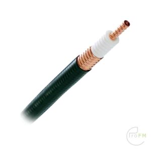
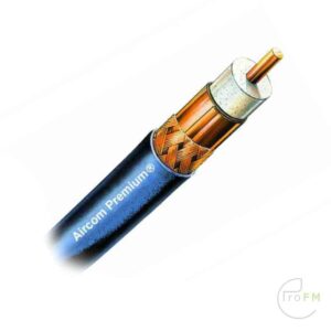
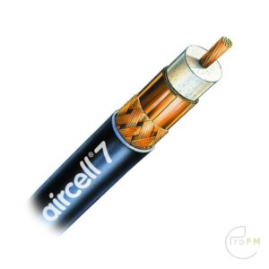
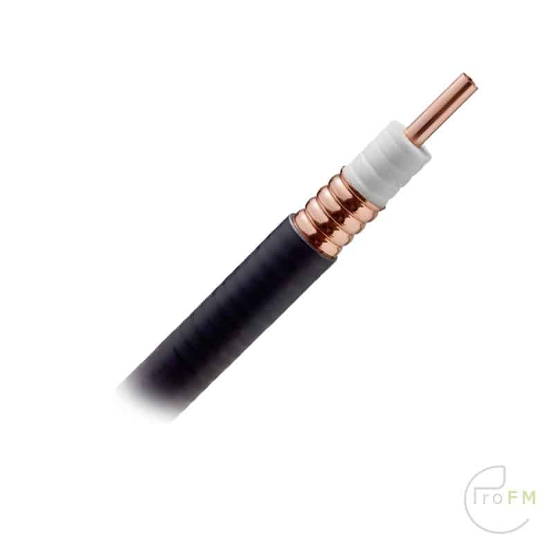
RFS Cellflex LCF78-50 Foam Coax Cable
The low attenuation of CELLFLEX coaxial cable results in highly efficient signal transfer in your RF system. Complete Shielding The solid outer conductor of CELLFLEX coaxial cable creates a continuous RFI/EMI shield that minimizes system interference. Low VSWR Special low VSWR versions of CELLFLEX coaxial cables contribute to low system noise.
Outstanding Intermodulation Performance CELLFLEX coaxial cable’s solid inner and outer conductors virtually eliminate intermods. Intermodulation performance is also confirmed with state-of-the-art equipment at the RFS factory. High Power Rating Due to their low attenuation, outstanding heat transfer properties and temperature stabilized dielectric materials, CELLFLEX cable provides safe long term operating life at high transmit power levels.
Wide Range of Application Typical areas of application are: feedlines for broadcast and terrestrial microwave antennas, wireless cellular, PCS and ESMR base stations, cabling of antenna arrays, and radio equipment interconnects.
Price per meter
Technical features
|
||||||
|
||||||||||||||||||||||||||||||
|
||||||||||||||||||
|
|||||||||||||||||||||||||||||||||||||||
|
|||||||||||||||||||||
|
||||||||||||||||||||||||||||||||||||||||||||||||||||||||||||||||||||||||
- Description
-
RFS Cellflex LCF78-50 Foam Coax Cable
The low attenuation of CELLFLEX coaxial cable results in highly efficient signal transfer in your RF system. Complete Shielding The solid outer conductor of CELLFLEX coaxial cable creates a continuous RFI/EMI shield that minimizes system interference. Low VSWR Special low VSWR versions of CELLFLEX coaxial cables contribute to low system noise.
Outstanding Intermodulation Performance CELLFLEX coaxial cable’s solid inner and outer conductors virtually eliminate intermods. Intermodulation performance is also confirmed with state-of-the-art equipment at the RFS factory. High Power Rating Due to their low attenuation, outstanding heat transfer properties and temperature stabilized dielectric materials, CELLFLEX cable provides safe long term operating life at high transmit power levels.
Wide Range of Application Typical areas of application are: feedlines for broadcast and terrestrial microwave antennas, wireless cellular, PCS and ESMR base stations, cabling of antenna arrays, and radio equipment interconnects.
Price per meter
- Specifications
-
Technical features
INFORMATION Applications Main feed line, intended for outdoor usage STRUCTURE Size 7/8 Inner Conductor Diameter mm (in) 9.1 (0.358) Inner Conductor Material Copper Tube Dielectric Diameter mm (in) 21.5 (0.846) Dielectric Material Foam Polyethylene Outer Conductor Diameter mm (in) 25.2 (0.992) Outer Conductor Material Corrugated Copper Jacket Diameter mm (in) 27.8 (1.094) Jacket Material Black Polyethylene TESTING AND ENVIRONMENTAL Phase Stabilized Phase stabilized and phase matched cables and assemblies are available upon request. Compliance DIN EN ISO 9001:2015 ISO 14001:2015
RoHS 2011/65/EU – China RoHS SJ/T 11364-2006
REACH (EC 1907/2006)
UL1581 – UV Resistance Jacket
IEC 60754-1/-2
Installation Temperature °C(°F) -40 to 60 (-40 to 140) Storage Temperature °C (°F) -70 to 85 (-94 to 185) Operation Temperature °C(°F) -50 to 85 (-58 to 185) ELECTRICAL SPECIFICATIONS Impedance Ω 50 +/- 1 Maximum Frequency GHz 5 Velocity % 88 Capacitance pF/m (pF/ft) 74 (22.5) Inductance uH/m (uH/ft) 0.185 (0.056) Peak Power Rating kW 85 RF Peak Voltage Volts 2920 Jacket Spark Volt RMS 8000 Inner Conductor dc Resistance Ω/1000 m (Ω/1000 ft) 2.04 (0.62) Outer Conductor dc Resistance Ω/1000 m (Ω/1000 ft) 1.55 (0.472) Passive Intermodulation PIM typ. dBc -160 Return Loss (VSWR) Performance Standard 20dB (1.222) / Premium 23/24dB (1.152/1.135) on specified frequencies MECHANICAL SPECIFICATIONS Cable Weight, Nominal kg/m (lb/ft) 0.39 (0.262) Minimum Bending Radius, Single Bend mm (in) 120 (5) Minimum Bending Radius, Repeated Bends mm (in) 250 (10) Bending Moment Nm (lb-ft) 13 (10) Tensile Strength N (lb) 1440 (324) Recommended / Maximum Clamp Spacing m (ft) 0.8 / 1 (2.75 / 3.25) ATTENUATION @ 20°C (68°F) AND POWER RATING @ 40°C (104°F) Frequency, MHz dB per 100m dB per 100ft Power, kW 1 0.11 0.03 87,96 100 1.17 0.36 8.5 200 1.68 0.51 5.92 450 2.58 0.79 3.85 700 3.28 1.00 3.03 800 3.53 1.08 2.82 900 3.76 1.15 2.64 1800 5.55 1.70 1.79 2000 5.89 1.80 1.69 2200 6.23 1.90 1.60 2400 6.55 2.0 1.52 2700 7.01 2.14 1.42 3000 7.46 2.28 1.33 3500 8.17 2.49 1.22 4000 8.84 2.70 1.12 5000 10.11 3.09 0.98